
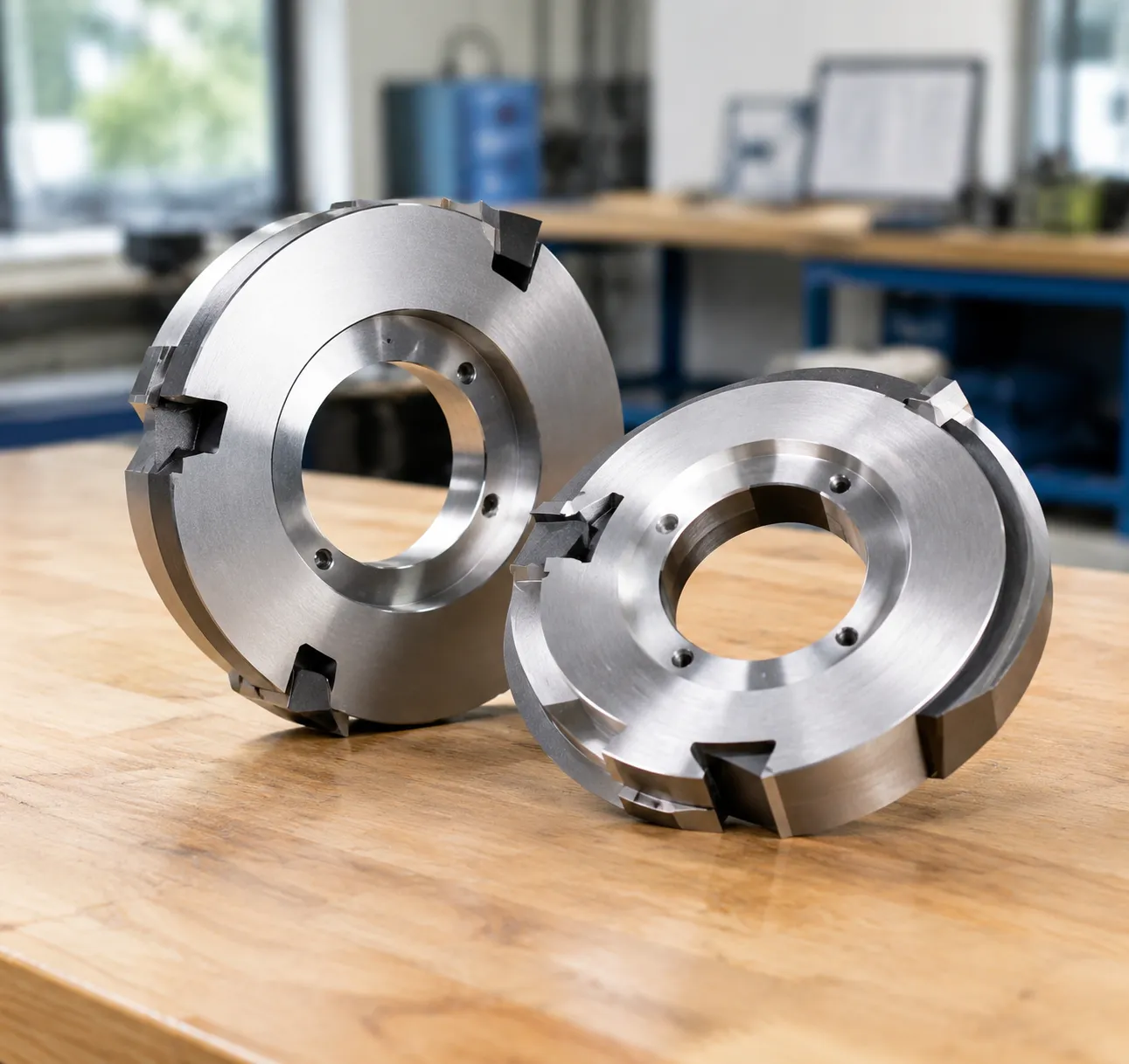
Formula details
Product Details
Overview
Top and Bottom Slitter Knives: Precision Rotary Shear Tooling
System Mechanics: Rotary Male and Female Knife Dynamics
Shear slitting functions through the precise mechanical engagement of two rotating components:
Top Slitter Knives (Male Blades): Positioned on the upper arbor, these rotary circular or dished knives provide the primary cutting edge.
Bottom Slitter Knives (Female Anvils): Mounted on the lower driven shaft or friction-fed mandrel, these flat, banded, or multi-groove rings act as the opposing cutting edge.
When the material passes through the dynamic shear point, the overlapping edges generate a controlled scissor action. Maintaining accurate overlap depth and cant angle ensures a clean separation without stretching, tearing, or generating edge debris.
Core Performance Advantages
- Tight Dimensional Tolerances: Consistent edge overlap eliminates web flutter, slitting offset, and uneven slit widths.
- Extended Wear Life: Advanced metallurgy and precision heat treatments prevent premature dulling, keeping machines online longer between blade regrinds.
- Minimized Edge Buildup: Precision-lapped surfaces reduce friction and material adhesion, preventing adhesive, resin, or polymer buildup at the cut zone.
- Dust and Burr Reduction: Sharp, micro-finished edges shear cleanly through fibrous papers, tough films, and thin metal foils without ragged edges.
Critical Engineering Specifications
| Parameter | Tooling Standard | Production Benefit |
|---|---|---|
| Thickness Tolerance | Up to ±0.002 mm (±0.00008") | Prevents axial drift and maintains slitting width accuracy |
| Surface Roughness | Ra 0.1 – 0.2 µm (Mirror Polish) | Minimizes adhesive drag and web friction |
| Radial / Axial Runout | Controlled within strict micrometer limits | Eliminates high-speed vibration and edge chatter |
| Balancing | Dynamically balanced for high-speed converting | Extends shaft bearing life and stabilizes high-speed lines |
Configuration and Geometries for Top and Bottom Slitter Knives
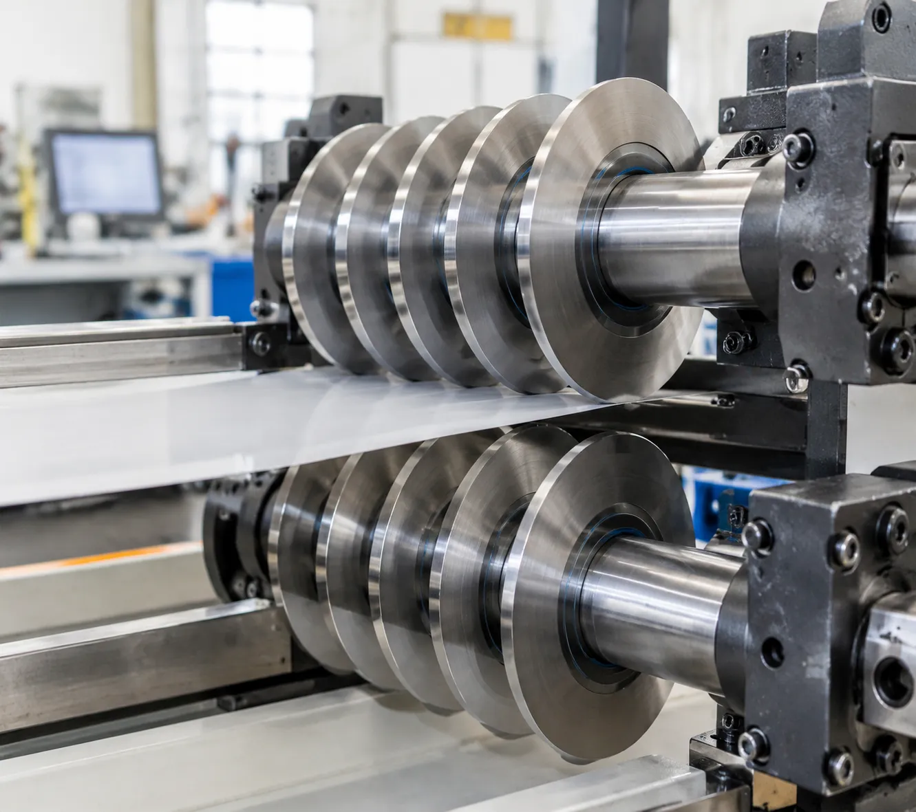
Top Slitter Knives: Dished and Flat Male Blades
Top slitter knives—often called male rotary blades—provide the initial shear action against the bottom anvil. Depending on web tension, material thickness, and arbor setups, we manufacture these in two core body styles and multiple cutting edge profiles:
- Dished Top Slitter Blades: Feature a concave body profile that provides built-in side-load spring tension against the bottom knife. This profile ensures consistent point contact at the cut point without generating excessive friction or premature edge roll.
- Flat Circular Blades: Built for rigid setups and high-caliper materials where deflection must be eliminated. Flat blades maintain precise vertical alignment across heavy-duty converting runs.
- Bevel Geometries:
- Single Bevel: Ideal for heavier stocks, rigid plastics, and paperboard, directing the cutting load away from the web edge. Choosing the right circular slitter knife bevel angle for paper cutting is critical to prevent fiber crush and trim buildup.
- Double Bevel: Balances cutting pressure symmetrically on both sides of the edge, making it the standard choice for films, foils, and thin barrier layers.
- Compound & Hollow-Ground Bevels: Minimize side friction and contact area, reducing adhesive pickup when slitting pressure-sensitive tapes and coated substrates.
| Top Blade Profile | Best Suited For | Key Operational Advantage |
|---|---|---|
| Dished (Single Bevel) | Paper, board, non-wovens | Self-compensating contact pressure |
| Dished (Double Bevel) | Flexible packaging, BOPP, PET | Low-friction shearing, minimal dust |
| Flat (Compound Bevel) | Adhesive tapes, label stock | Prevents adhesive bleed and edge drag |
| Flat (Heavy-Duty) | Metal foils, battery separators | Zero blade deflection at high web tension |
Bottom Slitter Knives: Single-Edge, Double-Edge, and Multi-Groove Anvils
The female anvil supports the web and provides the sharp counter-edge required for true shear cutting. We manufacture bottom anvil knives to tight axial tolerances to prevent lateral runout and web pinching:
- Single-Edge Anvils: Dedicated high-precision rings designed for fixed-width production runs where edge stability is paramount.
- Double-Edge Reversible Anvils: Feature ground cutting edges on both outer corners. When one side wears down, operators can flip the knife on the shaft, effectively doubling tool life before regrinding is required.
- Multi-Groove Female Slitter Rings: Designed with multiple precision-machined cutting grooves on a single sleeve. These allow rapid width adjustments across standard slitting patterns without having to individually reposition dozens of separate knife bodies.
Split and Segmented Designs for Quick Changeovers
Full shaft teardowns cause unnecessary downtime on high-volume converting lines. To solve this, we manufacture two-piece split bottom anvils and segmented knife collars.
- Fast Assembly: Precision interlocking dovetail or bolted split configurations allow operators to clamp bottom knives directly onto the shaft at any position.
- Zero Arbor Disassembly: Adjust slit widths or replace worn cutting rings without removing bearings, pulleys, or neighboring tooling.
- Matched Precision: Each split pair is CNC-ground as an assembled unit, maintaining the same radial runout limits and OD concentricity as solid circular slitter knives.
Metallurgy Guide: Matching Tool Steel to Web Substrates
Choosing the right alloy for your top and bottom slitter knives prevents premature dulling, slitter dust, and edge burrs. We match blade metallurgy directly to your continuous web material, line speed, and operating environment to maximize blade life between sharpenings.
D2 and SKD11 Tool Steel: High Wear Resistance for Standard Webs
- Material Profile: High-carbon, high-chromium cold-work tool steel (1.2379 / SKD11 / Cr12MoV).
- Performance: Exceptional abrasive wear resistance and dimensional stability under continuous shear pressure.
- Best Suited For: Standard paper converting, cardboard, corrugated packaging, and commodity plastic films (BOPP, PET, PE, PVC).
High-Speed Steel (M2 and M42): Superior Shock Resistance and Edge Retention
- Material Profile: M2 (1.3343 / SKH51) and cobalt-alloyed M42 high-speed steels.
- Performance: Superior thermal stability and micro-chipping resistance during high-speed converting runs. Edge profiles stay sharp significantly longer than standard tool steels when running abrasive materials. For best results on high-speed paper lines, balance your material choice with our recommended shear slitting top knife bevel angle for paper.
- Best Suited For: Abrasive coated papers, heavy non-wovens, and demanding packaging lines.
Powder Metallurgy and Tungsten Carbide: Maximum Run-Life
- Material Profile: Solid Tungsten Carbide (TCT), carbide-inlaid cutting edges, and ASP powder metallurgy steels.
- Performance: Ultra-fine grain structure and extreme hardness that eliminate micro-burrs and resist wear across millions of shear cycles.
- Best Suited For: Lithium-ion battery cathode/anode foils (aluminum and copper), separator films, magnetic media, and ultra-thin technical films.
Martensitic Stainless Steel: Cleanroom-Ready Corrosion Resistance
- Material Profile: Precision-hardened 420 and 440C stainless steel.
- Performance: 100% rust-resistant and chemically inert cutting edges that hold a fine, mirror-polished shear geometry without flaking or oxidizing.
- Best Suited For: Food-grade packaging, medical device converting, sanitary tissue, and moisture-prone slitting environments.
Material Selection Summary
| Material Grade | Key Metallurgy Advantage | Recommended Web Applications |
|---|---|---|
| D2 / SKD11 | Cost-effective, high wear resistance | Standard paper, board, PE, PET, PVC |
| HSS M2 / M42 | High toughness, shock resistance, edge retention | Coated papers, high-speed lines, abrasive webs |
| Tungsten Carbide / ASP | Extreme hardness, zero burr tolerance, maximum run-life | Battery foils, copper/aluminum, thin barrier films |
| Stainless 420 / 440C | Complete rust and corrosion resistance | Food packaging, medical non-wovens, cleanrooms |
Engineering Tolerances and Quality Manufacturing Standards
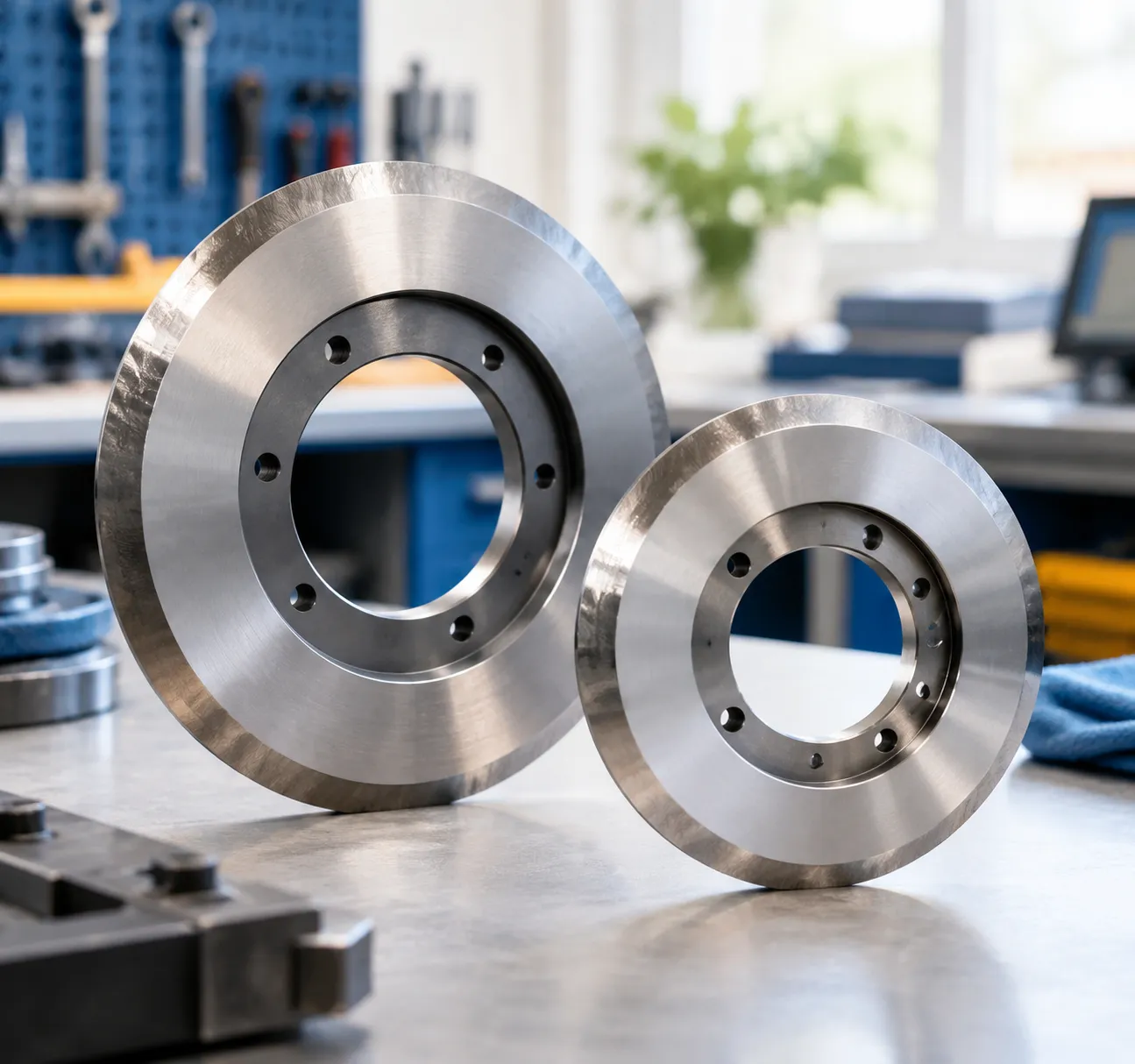
Slitter dust, irregular edge burrs, and premature wear almost always trace back to poor manufacturing tolerances or improper metallurgical processing.
| Manufacturing Standard | Production Impact & Operational Benefit |
|---|---|
| Strict Runout Control | Eliminates blade wobble, edge burrs, and web flutter |
| Deep Cryogenic Treatment | Removes retained austenite for zero thermal warping |
| Mirror Lapped Finish | Stops adhesive buildup and minimizes slitter dust |
Runout Control: Eliminating Web Flutter and Edge Variation
Rotary shear slitting requires consistent contact between the male top blade and female bottom anvil. Even minor radial or axial runout causes blade wobble, shifting the shear point and creating web flutter, uneven slit widths, and edge fraying.
- Minimal Axial Runout: Eliminates lateral blade drift, maintaining a steady overlap and contact pressure.
- Tight Radial Tolerances: Keeps the cutting circumference perfectly round, preventing periodic edge pinching or micro-tears.
- Strict Parallelism & Thickness Limits: Ensures seamless stacking on multi-knife shafts and exact knife spacing across the web.
Every batch undergoes comprehensive dimensional verification through our dedicated slitter blade quality control systems to ensure drop-in reliability.
Deep Cryogenic Treatment for Long-Term Dimensional Stability
Standard heat treatment can leave behind microscopic pockets of retained austenite, which cause blades to warp or lose edge hardness as friction heat builds during operation. We incorporate deep cryogenic processing directly into our thermal cycles:
- Austenite-to-Martensite Transformation: Sub-zero freezing stabilizes the crystalline matrix of the steel, locking in core toughness.
- Zero Warping Under Load: Prevents dimensional distortion when slitter knives run continuously at high line speeds.
- Extended Edge Retention: Enhances overall wear resistance, drastically extending operating cycles between scheduled regrinds.
Our specialized approach to D2 tool steel heat treatment and advanced alloy hardening provides the exact metallurgical structure needed for heavy-duty converting.
Precision Lapping and Mirror Finishes: Minimizing Slitter Dust
The surface texture of a slitter knife directly affects how materials interact with the blade edge during shearing. Rough grinding marks create friction, pull fibers, and collect sticky residues.
- Mirror-Polished Cutting Edges: Precision lapping produces ultra-smooth blade faces that slice through substrates cleanly without tearing.
- Dust Reduction: Clean edge separation drastically cuts down on airborne debris when converting paper, tissue, and non-wovens.
- Adhesive Buildup Prevention: Low-friction finishes prevent pressure-sensitive adhesives, polymers, and coatings from sticking to the knife body, keeping downtime for blade wipe-downs to a minimum.
Industrial Applications and Material Compatibility for Top and Bottom Slitter Knives
Flexible Packaging and Plastic Films
Slitting thin polymer films requires sharp, polished cutting edges to prevent edge curling, stretching, and micro-tears.
Target Materials: BOPP, PET, multilayer barrier films, PE, and PVC.
Tooling Setup: Razor-honed dish top knives paired with mirror-finished bottom anvil rings.
Key Benefit: Eliminates tensile deformation and provides clean, slip-free separation across high-speed rewinders. For comprehensive web converting systems, explore our complete range of shear slitting knives tailored for thin films.
Paper, Tissue, and Corrugated Board
High-volume paper converting generates massive amounts of airborne dust if the knife bevel and shear point are not perfectly aligned.
Target Materials: Newsprint, thermal paper, kraft paper, folding carton board, and tissue.
Tooling Setup: D2 or M2 high-speed steel male blades paired with multi-groove female bottom shafts.
Key Benefit: Sharp, wear-resistant cutting profiles cut cleanly through fibers, dramatically reducing slitter dust buildup and preventing roll-edge roughness.
Battery and Clean Energy Substrates
Battery manufacturing leaves zero room for edge defects. Burrs or flaking on current collector foils can puncture separators and trigger short circuits.
Target Materials: Lithium-ion copper anode foil, aluminum cathode foil, and microporous separator films.
Tooling Setup: Solid tungsten carbide rotary slitting knives with sub-micron edge finishes.
Key Benefit: Delivers completely burr-free edges, zero metal delamination, and ultra-tight width tolerances under continuous cleanroom operations.
Technical Non-Wovens and Coated Textiles
Non-woven fabrics and pressure-sensitive tapes combine abrasive synthetic fibers with sticky adhesives that quickly degrade standard blades.
Target Materials: Spunbond, meltblown polypropylene, fiberglass-reinforced tape, rubber, and medical adhesive textiles.
Tooling Setup: Tungsten carbide or cryogenic-treated HSS knives with specialized mirror-lapped side faces.
Key Benefit: Resists edge rounding against abrasive polymers while preventing adhesive pick-up on the blade body.
| Substrate Category | Key Slitting Challenge | Recommended Blade Material | Slitter Configuration |
|---|---|---|---|
| BOPP / PET Films | Edge stretch, micro-cracks | HSS (M2 / M42) | Dished top blade + Polished bottom anvil |
| Paper & Cardboard | Dust generation, fiber pull | D2 / Cr12MoV | Single/Double bevel top + Multi-groove shaft |
| Battery Metal Foils | Edge burrs, particulate shed | Solid Tungsten Carbide | Ultra-low runout male + Female knife pair |
| Coated Non-Wovens | Adhesive buildup, abrasive wear | Tungsten Carbide / HSS | Mirror-finish top knife + Hardened bottom ring |
Custom OEM Fabrication and Replacement Workflow for Top and Bottom Slitter Knives
Drop-in OEM Replacements for Converting Lines
When production slows down due to worn cutting edges or shaft fitting issues, you need exact-match replacement blades that integrate directly into your slitter-rewinder without machine modification. We engineer precision top and bottom slitter knives designed to fit standard rotary shear converting setups across paper, film, foil, and textile lines.
Through our specialized OEM industrial knives manufacturing workflow, we supply exact-fit male top slitters, multi-groove anvil shafts, and split bottom rings that meet or exceed original equipment wear life and dimensional tolerances.
Precision Engineering Workflow
Whether you need a direct replacement based on original equipment part numbers or require an altered bevel geometry to eliminate slitter dust on abrasive webs, our custom engineering team handles the process from print to finished blade:
- CAD Print Evaluation: Upload technical drawings (.DXF, .DWG, .STEP, or PDF) for rapid metallurgical evaluation, tolerance verification, and quote generation.
- Sample Reverse Engineering: If CAD files are unavailable, ship us a new or worn blade sample. We map keyway dimensions, bore diameters, bevel angles, and metallurgy to replicate exact operational profiles.
- CNC Machining & Precision Grinding: Blades are shaped on multi-axis CNC machines and precision-ground to maintain ultra-tight thickness and runout tolerances.
| Production Step | Technical Execution | Operational Advantage |
|---|---|---|
| Material Sourcing | High-grade D2, M2 HSS, or solid Tungsten Carbide | Maximizes wear resistance and edge toughness |
| Heat Treatment | Vacuum hardening with sub-zero cryogenic stabilization | Prevents tool deformation under continuous load |
| Finish Grinding | Fine-grit CNC edge grinding and face lapping | Prevents web drag, adhesive pickup, and edge burrs |
Traceability and Quality Control Standards
Every top and bottom slitter blade undergoes rigorous quality verification before leaving our facility to ensure dynamic balance and consistency across multi-knife setups:
- CMM Dimensional Verification: Coordinate measuring machines inspect outside diameters, bore concentricity, and axial/radial runout to eliminate slitter wobble at high web speeds.
- Surface & Hardness Testing: Digital hardness testers confirm Rockwell (HRC) ratings across all tool steels and carbide grades.
- Laser Etching & Part Serialization: Every knife is permanently marked with material grade, production lot, and part numbers for complete supply-chain tracking and simplified reordering.
Operational Best Practices and Troubleshooting Slitter Defects
Even the highest-grade tooling underperforms if your slitting geometry is off by a fraction of a millimeter. To get clean separation, zero edge contamination, and the longest run-life out of our top and bottom slitter knives, your setup parameters must stay strictly controlled.
Setup Optimization: Dialing in Cant Angle, Overlap, and Depth
Getting consistent shear action requires balancing three critical mechanical settings:
- Cant Angle (Shear Angle): Set your top blade angle between 0.25° and 0.5° relative to the bottom anvil. Too much angle leads to heavy side friction and blade chipping; too little causes the web to wedge between the blades.
- Vertical Overlap (Depth of Engagement): Overlap should match substrate thickness. For thin films and foils, set vertical overlap between 0.010" to 0.020" (0.25 mm to 0.50 mm). Heavy paperboard or thick plastics may require up to 0.040" (1.0 mm). Excessive depth accelerates edge wear and creates slitter dust.
- Side-Load (Horizontal Force): Apply just enough spring or pneumatic pressure to maintain positive contact at the shear point. Over-tightening causes rapid dulling, excessive heat, and localized micro-cracking.
Diagnosing Slitter Defects: Quick Fixes for Clean Web Converting
When slitting quality drops on the line, use this diagnostic breakdown to isolate and fix the root cause immediately:
| Slit Defect | Probable Root Cause | Immediate Corrective Action |
|---|---|---|
| Edge Burrs / Scalloping | Dull blade edge, excessive knife clearance, or loose blade collars | Resharpen cutting edge; recalibrate overlap and check our slitter blade troubleshooting guide to eliminate shaft play. |
| Heavy Slitter Dust | Excessive vertical overlap or blunt edge crushing the fibers/polymer | Reduce blade penetration; verify cant angle is not plowing into the anvil face. |
| Premature Edge Chipping | Excessive side-load pressure, severe shaft runout, or web vibration | Lower side-load force; inspect shafts for dynamic runout; switch to tougher HSS or shock-resistant carbide grades. |
| Web Slit Width Variation | Axial wobble on female anvil rings or loose set screws | Clean shaft seats, verify axial runout within ±0.002 mm, and torque collars to spec. |
Regrinding and Sharpening Protocols
Proper knife maintenance restores original tool performance without sacrificing dimensional integrity:
- Maintain Matched Diameters: When regrinding multi-knife setups, always grind top and bottom slitter sets in uniform batches to ensure consistent surface speeds across all slit lanes.
- Restore Factory Edge Profiles: Grind single and double bevels strictly to original factory angles using fine-grit CBN wheels for D2/HSS tooling and diamond wheels for tungsten carbide slitter knives.
- Surface Relapping: Always lap and mirror-polish the shear faces after grinding. Removing grind lines prevents polymer buildup, adhesive transfer, and micro-drag along the slit edge.
Frequently Asked Questions About Top and Bottom Slitter Knives
What is the ideal cant angle and blade overlap for thin film shear slitting?
For flexible plastic films, foils, and coated webs, maintaining precise geometry prevents tear-out and blade wear:
- Cant Angle (Toe-in): Typically set between 0.25° and 0.5° (15 to 30 minutes of arc). Excessive angle creates heavy friction, rapid blade dulling, and heat buildup, while zero angle leads to blade chatter and rough slitting.
- Vertical Overlap (Depth): Generally set between 0.015 in and 0.030 in (0.38 mm to 0.76 mm). Thinner gauges (like BOPP and PET) require shallower penetration to avoid edge deformation when using high-speed film cutting knives.
- Side Load Pressure: Minimal spring or pneumatic pressure sufficient to maintain continuous shear contact without deflecting the rotary knife edge.
When should I choose Tungsten Carbide over High-Speed Steel (M2)?
Material selection comes down to balancing abrasion resistance against mechanical shock and operating conditions:
| Parameter | High-Speed Steel (M2 / M42) | Solid Tungsten Carbide (TCT) |
|---|---|---|
| Wear Resistance | Moderate to high | Maximum (up to 10–50x longer tool life) |
| Impact / Shock Toughness | High (resists chipping from line vibration) | Low to moderate (requires rigid slitting assemblies) |
| Recommended Web Types | Standard paper, non-wovens, general plastics | Battery electrode foils, magnetic media, glass fiber, abrasive coatings |
| Line Speed Capability | Standard to high converting speeds | Continuous high-speed runs with minimal changeovers |
For deeper metallurgical comparisons, check our technical breakdown in the carbide vs steel knives guide.
Can top and bottom knives be custom-manufactured from worn samples or CAD drawings?
Yes. We regularly fabricate drop-in replacement blades from either:
CAD/CAM Files: Direct production from 2D (DXF, DWG, PDF) and 3D (STEP, IGES) prints with exact tolerances for bore, OD, thickness, and bevel angles.
Worn Sample Reverse Engineering: We analyze physical blades using coordinate measuring machines (CMM) and optical profile projectors to reconstruct original factory geometries, including OEM-specific keyways, multi-groove pitches, and dish profiles.
How do I know whether my slitter knives need regrinding or full replacement?
Monitoring dimensional limits and cutting edge conditions determines the right service step:
- Regrind: The blade has minor micro-chipping, slight dulling, or light edge wear, and the outer diameter (OD) remains within your slitter-rewinder's vertical adjustment travel.
- Full Replacement: The blade reaches its minimum scrap OD limit, exhibits thermal cracking/spalling, has a damaged or loose bore/arbor fit, or bottom anvil grooves have worn beyond allowable axial tolerances.
What causes slitter dust and edge burrs during high-speed converting?
Slitter dust and burrs stem from four primary mechanical and tooling issues:
Excessive Runout: Axial or radial runout exceeding 0.005 mm causes intermittent shearing, pounding the web rather than cleanly slicing it.
Dull or Chipped Edges: Worn knife radiuses pinch and crush the web, fracturing the substrate fibers or stretching plastic films.
Incorrect Overlap and Side Pressure: Excessive penetration creates a plow effect that generates debris, while insufficient side load allows the material to slip between the blades.
Mismatched Bevel Angles: Using a blunt single bevel where a hollow-ground or double-bevel geometry is required increases web displacement resistance.
Related Sources
- https://www.maxcess.com/slitting/
- https://www.hydeblades.com/materials-metallurgy/
- https://www.sciencedirect.com/science/article/pii/S092401362030283X
- https://convertingquarterly.com/slitting-fundamentals-optimizing-shear-slitting-performance/
- https://carolinaknife.com/blades/circular-knives/shear-slitter-blades/