
How Rotary Shearing Cuts Metal
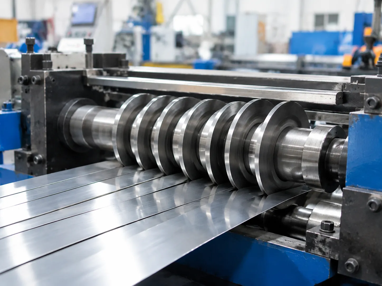
Rotary slitting divides wide master coils into precise, narrow metal strips using continuous rotary shear mechanics. Unlike conventional guillotine shearing—which uses a straight, stationary blade stroke across a fixed sheet—rotary knife cutting relies on pairs of opposed circular blades mounted on parallel rotating arbors. The strip moves continuously between the upper and lower rotary slitter knives, producing smooth, high-speed lengthwise cuts.
Opposed Circular Shearing vs. Guillotine Shearing
| Shearing Method | Cutting Action | Best Suited For | Continuous Coil Operation? |
|---|---|---|---|
| Rotary Shearing | Continuous counter-rotating circular knives | High-speed master coil slitting into narrow mults | Yes |
| Guillotine Shearing | Single linear stroke with straight upper/lower blades | Sizing flat sheets to length | No (Batch/Stop-Motion) |
Driven Knife Action vs. Pull-Through Slitting
Metal slitting lines typically apply one of two mechanical drives:
- Driven Knife Slitting: The slitter arbors are actively powered by a synchronized drive motor. This setup provides exact speed synchronization, minimizes strip slippage, and handles delicate thin foils or heavy structural gauges without stretching the strip.
- Pull-Through Slitting: The knives freewheel on idle arbors while the downstream recoiler pulls the metal coil through the slitter head under high tension. This method simplifies line mechanics but requires strict tension management to avoid edge tearing.
The Three Phases of the Shearing Cycle
Rotary knives do not slice all the way through the metal strip. Instead, they initiate a progressive mechanical failure sequence:
- Phase 1: Elastic and Plastic Deformation
As the rotating knives pinch the top and bottom of the strip, the metal initially deforms elastically. Once cutting force exceeds the material's yield strength, plastic deformation sets in, creating a slight, smooth curve known as the rollover edge. - Phase 2: Knife Penetration and Burnish Band Formation
The cutting edges penetrate into the upper and lower surfaces of the metal. As the blades displace the material, they generate a bright, smooth, vertical band known as the burnish depth (typically spanning 15% to 40% of strip thickness depending on temper). - Phase 3: Controlled Stress Fracture and Clean Strip Separation
Continued penetration creates extreme shear stresses at the cutting tips. Micro-cracks propagate inward from the upper and lower knife points. When these opposing crack fronts meet within the shearing fracture zone, the material snaps cleanly along the cut line, separating the master coil into distinct metal strip mults.
- Phase 1: Elastic and Plastic Deformation
Key Components of a Slitter Arbor Setup
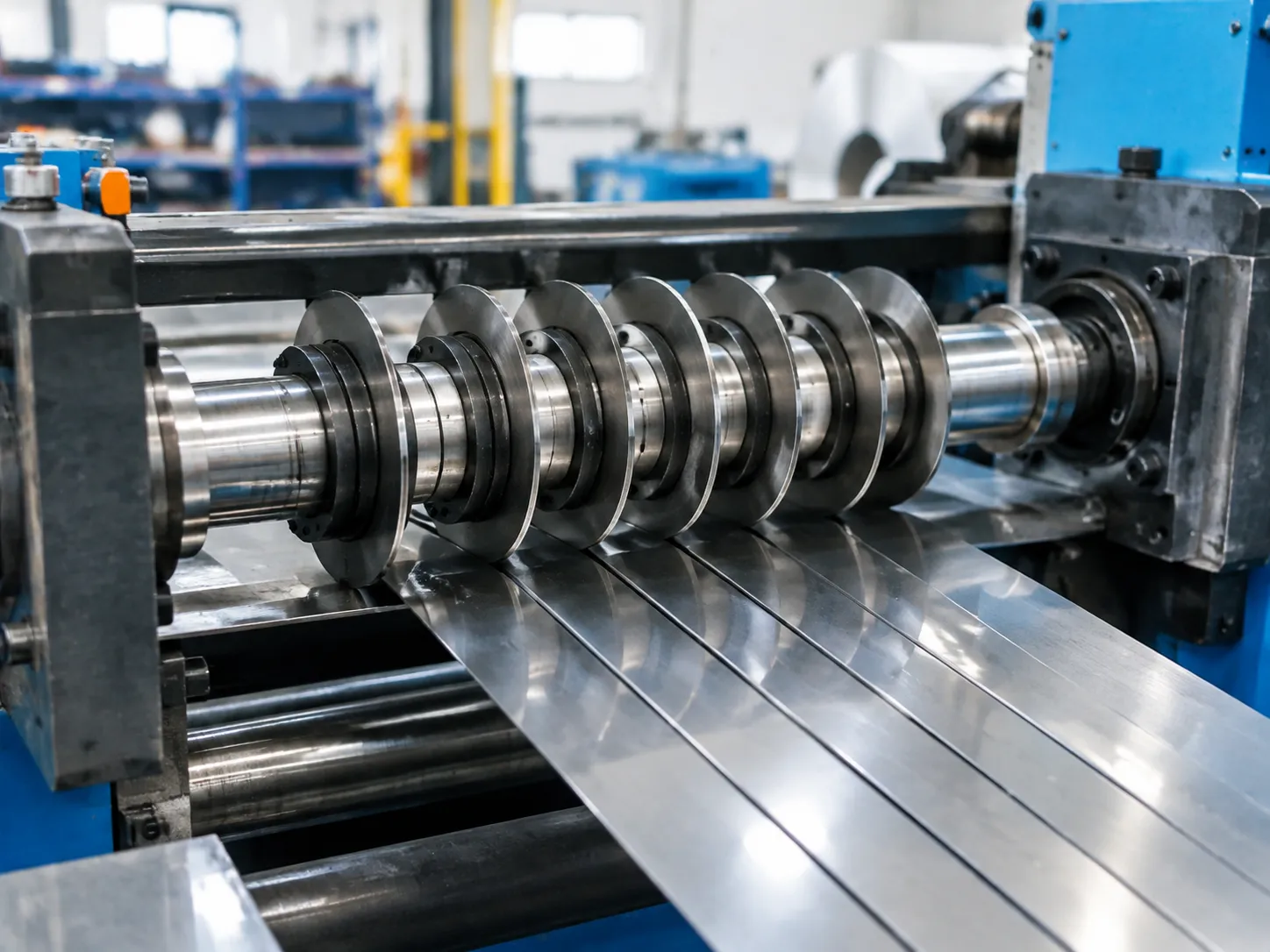
To understand how rotary knife cutters work for metal slitting, you have to look at the tooling stack loaded onto the machine. Every component on the arbor plays a direct role in maintaining tight clearances, preventing deflection, and ensuring clean edge separation across every cut.
Here is the core hardware we use to build a rigid, high-precision slitter arbor setup:
1. Rotary Slitter Knives
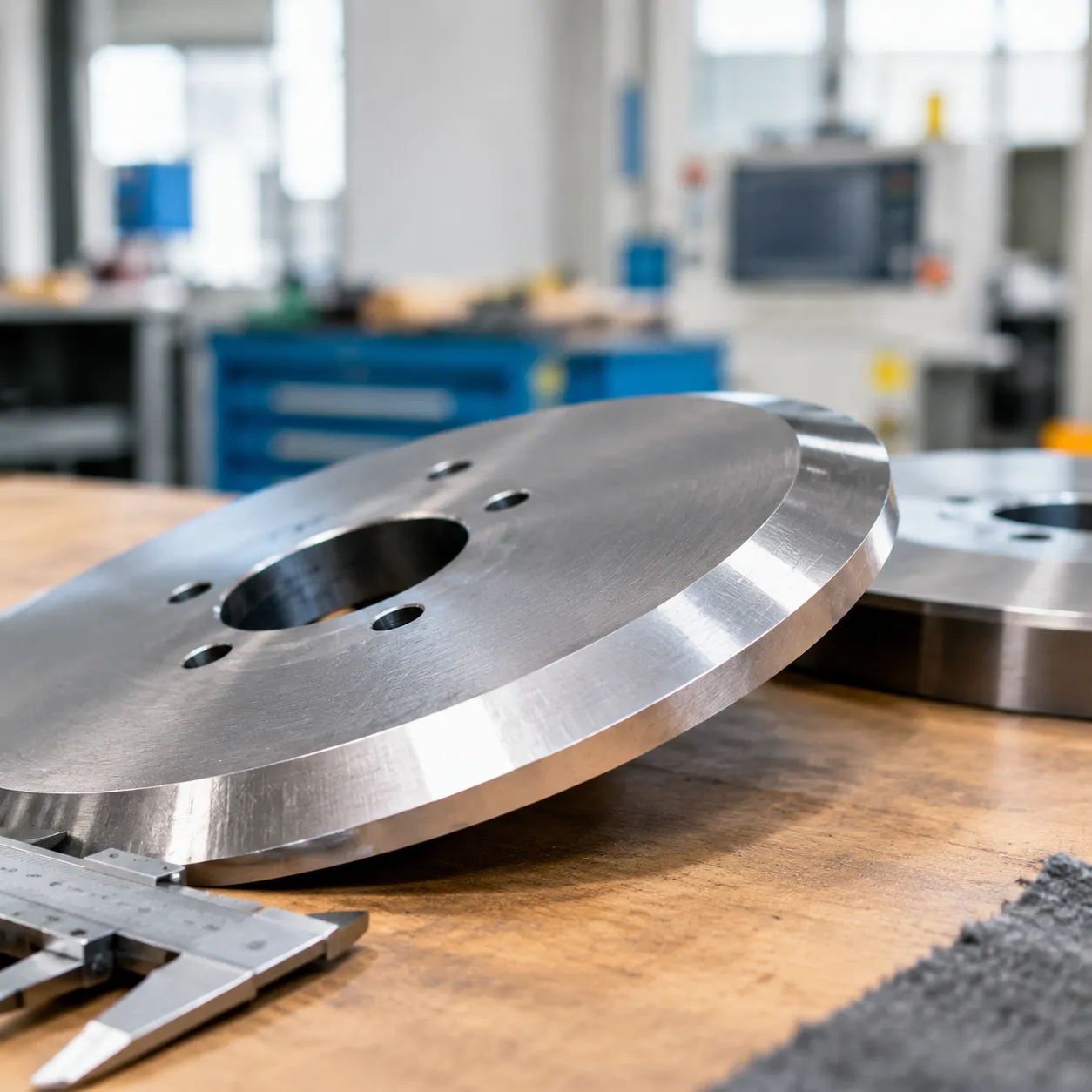
These are the heart of the cutting operation. Rotary knives are circular shearing blades that mount in opposing pairs on the top and bottom arbors. We manufacture and select these blades based on material gauge, hardness, and production volume:
Tool Steel Blades (D2, H13, M2): Standard for carbon steel, stainless, and non-ferrous coils, offering great impact resistance and dependable edge toughness. Check our slitter blade material guide to match specific steel grades to your coil specs.
Tungsten Carbide Blades: Built for ultra-precise, abrasive, or continuous high-speed runs where wear resistance is critical. Explore our custom precision sheet metal slitter knives for heavy-duty and tight-tolerance production lines.
2. Precision Tooling Spacers and Shims
Spacers position the knives along the arbor shaft to set the exact width of your finished metal strip mults:
Hardened Steel Spacers: Ground to parallel tolerances within 0.002 mm to keep knife faces perfectly square to the strip.
Lightweight Aluminum or Polyurethane Spacers: Used on larger diameter setups to reduce total arbor weight without losing dimensional accuracy.
Micro-Shims: Plastic or stainless shims used for fine-tuning horizontal knife clearance down to the micron.
3. Polyurethane and Rubber Stripper Rings
Stripper rings (also called male and female rings) slide directly adjacent to the knives to control metal movement during the cut:
Material Hold-Down: They clamp the incoming strip flat against the arbor tooling to eliminate flutter and twisting.
Positive Ejection: They push the slit mults out from between the knife faces, preventing material from wedging, jamming, or deforming under high line tension.
Durometer Selection: Harder durometers (70–90 Shore A) handle heavier gauge metals, while softer compounds protect sensitive surfaces from cosmetic marking.
4. Heavy-Duty Slitter Arbors
The arbors are the parallel driven shafts that hold the entire tooling assembly under extreme rotational and clamping pressure:
Deflection Resistance: Forged from high-grade alloy steels to eliminate shaft bending across wide master coils.
Runout Control: Machined to strict total radial and axial runout tolerances (under 0.005 mm) to prevent clearance drift, uneven burrs, or blade chipping during high-speed shearing.
Critical Tooling Variables for Clean Cuts
To understand how rotary knife cutters work for metal slitting at peak performance, you have to master the mechanical relationship between the upper and lower blades.
Horizontal Clearance: Setting the Side Gap
Horizontal clearance is the lateral space between the cutting edges of the upper and lower rotary slitting knives. Instead of blades physically contacting each other, proper shearing requires a controlled side gap that concentrates mechanical stress along the fracture line.
- Standard Rule: Set horizontal clearance between 7% and 15% of the metal strip thickness, depending on the tensile strength of the material.
- Mild and Soft Metals (e.g., Aluminum, Low-Carbon Steel): Require tighter clearance (around 7% to 9%) to prevent excessive edge rollover and burrs.
- High-Tensile and Stainless Steels: Need wider clearance (10% to 15%) to allow the natural fracture to propagate cleanly without overloading the slitter arbors.
- The Risk of Improper Gap: Setting the gap too narrow causes double shearing and rapid knife wear. Setting it too wide creates massive burrs and excessive edge droop. While compression methods detailed in our crush slitting guide rely on direct contact pressure, rotary metal shear slitting strictly depends on this precision offset.
Vertical Overlap: Controlling Penetration Depth
Vertical overlap refers to how deep the top blade extends past the edge of the bottom blade. Correct vertical positioning ensures the knives penetrate just deep enough to trigger the natural fracture cycle of the coil slitting process.
- Light-Gauge Strips (under 1.0 mm): Require positive overlap (the knives cross over each other by 0.25 mm to 0.75 mm) to establish the initial cut.
- Medium-Gauge Strips (1.0 mm to 3.5 mm): Typically run with near-zero to minimal positive overlap (0.00 mm to 0.20 mm).
- Heavy-Gauge Strips (over 4.0 mm): Often operate with negative overlap (open gap), where the blade faces do not cross vertically. The hydraulic downward force and material stiffness cause the strip to fracture before the knives ever bypass one another.
| Material Thickness | Target Horizontal Clearance | Recommended Vertical Overlap |
|---|---|---|
| Light Gauge (< 1.0 mm) | 7% – 9% of thickness | +0.25 mm to +0.75 mm (Positive) |
| Medium Gauge (1.0 – 3.5 mm) | 9% – 12% of thickness | 0.00 mm to +0.20 mm (Flush/Slight) |
| Heavy Gauge (> 3.5 mm) | 12% – 15% of thickness | -0.25 mm to -1.00 mm (Negative/Open) |
Passline Alignment: Eliminating Edge Scuffing and Distortion
The passline is the horizontal plane at which the metal strip enters and exits the slitter arbor setup. If the metal enters or leaves the knives at an uncalibrated angle, edge quality degrades immediately.
- Entry Angle Control: Keep the incoming strip flat and centered. An upward or downward tilt forces the strip against the knife sidewalls, causing edge friction and premature dulling.
- Exit Angle & Stripper Ring Positioning: Ensure the slit mults exit horizontally. Polyurethane stripper rings must be sized accurately to support the strip precisely at the shear point, preventing the metal from rubbing against the side faces of the tool steel circular blades.
- Preventing Edge Scuffing: Misaligned passlines create uneven burrs on opposite sides of the strip, generate edge camber, and introduce severe scuff marks on sensitive polished or coated metal surfaces.
Step-by-Step Metal Slitting Process Flow
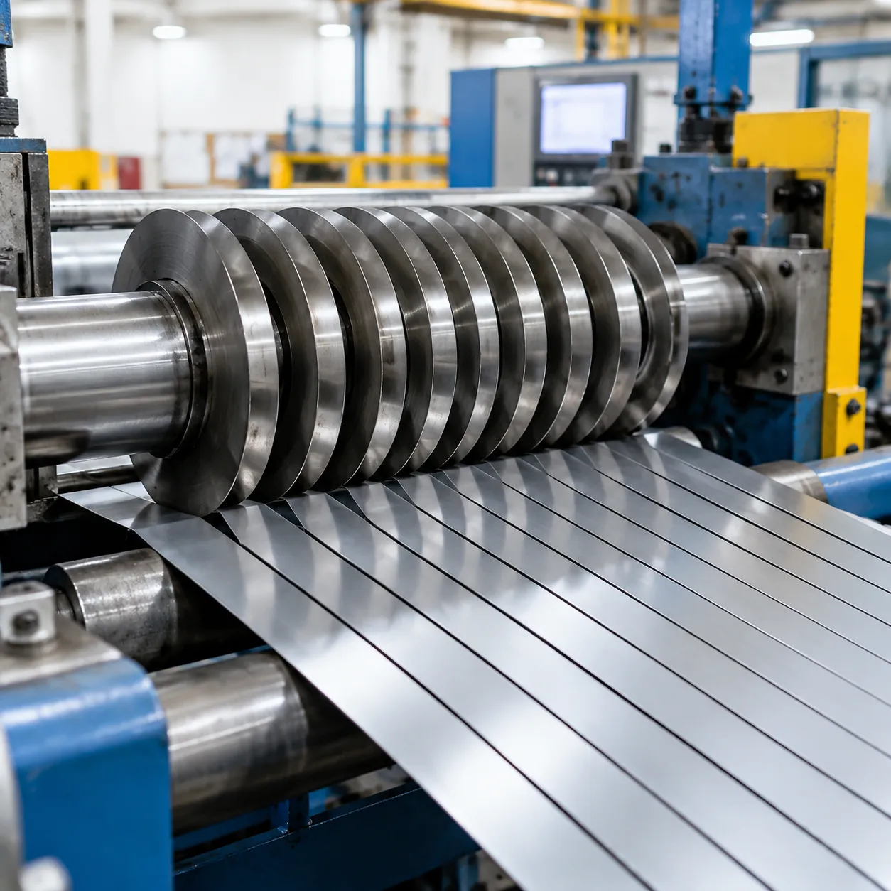
Running a metal slitting line requires strict adherence to setup charts and tension control. Here is how we break down the operational workflow from raw coil to finished slit strips.
1. Uncoiling, Leveling, and Setting Master Strip Tension
We mount the master coil onto the uncoiler mandrel, expand the hydraulic drum, and feed the lead edge directly into the flattener or precision leveler. Eliminating coil set and surface curvature before the material reaches the knives is critical. Once leveled, we engage the entry drag brake to apply controlled back-tension, preventing strip flutter and slack during high-speed cutting.
2. Loading Arbor Tooling According to the Slitting Chart
Every slitting program depends on an exact tooling buildup. We slide precision spacers, stripper rings, and rotary slitting knives onto the parallel arbors based on the target strip widths and clearance calculations.
- Tooling Inspection: We clean all knife faces and spacer surfaces to eliminate debris that causes axial runout.
- Locking the Arbors: We torque the arbor locking nuts to secure the tooling stack and set the vertical blade overlap.
| Setup Step | Target Parameter | Primary Function |
|---|---|---|
| Tooling Stacking | Width tolerance within +/-0.02 mm | Establishes precise cut mult dimensions |
| Arbor Lockup | Axial runout under 0.005 mm | Prevents knife wobble and burr spikes |
| Clearance Check | 7% to 15% of metal gauge | Ensures clean fracture mechanics |
3. Strip Entry and Engagement Under Controlled Back-Tension
The strip enters the slitter head via guided entry rolls. As the lead edge meets the rotating upper and lower blades, back-tension keeps the metal flat against the passline. This stops edge scuffing and prevents the material from wandering off-center as it penetrates the cut zone.
4. Continuous Rotary Shearing and Side Scrap Trimming
The knives rotate in opposing directions to pull and shear the strip simultaneously into targeted mults. Edge trim knives remove non-uniform outer edges on both sides. We direct these side scrap ribbons immediately into scrap winders or rotary scrap choppers to maintain continuous line speeds without tangling.
5. Recoiling Slit Mults Using Separator Tooling
Once sheared, the individual slit mults pass through tension stands—such as pad tensioners or roll bridles—to equalize slack caused by coil crown variations. We route each strip through precision separator discs mounted on overarm shafts before locking them onto the recoiler mandrel. These separator tools keep the finished slit coils aligned, preventing edge interweaving as the mults wind under full tension.
Slit Edge Quality and Troubleshooting Common Defects
Understanding how rotary knife cutters work for metal slitting means knowing what a good cut looks like on the cross-section. When your tooling setup is dialed in, the slit edge should display four distinct zones:
- Rollover (5%–10%): The slight rounded curve at the top where the blade first depresses the material.
- Burnish / Cut Band (20%–30%): The bright, smooth, vertical shear band formed during initial penetration.
- Fracture Zone (60%–70%): The matte, slightly granular surface where stress cracks meet and separate the metal.
- Burr (Under 5% of thickness): The small ridge at the bottom exit point, kept to an absolute minimum.
When the cut drifts away from these ratios, use this quick troubleshooting guide to diagnose and fix the root cause:
| Defect | Root Cause | Corrective Action |
|---|---|---|
| Excessive Slit Edge Burr | Dull knife edges, excessive horizontal knife clearance, or insufficient strip tension. | Regrind dull blades and tighten horizontal side clearance back to specification. |
| Edge Camber (Strip Curvature) | Uneven stripper ring pressure or mismatched ring durometer across upper and lower arbors. | Match stripper ring diameters and ensure equal clamping pressure on both sides of the cut. |
| Deep Rollover & Edge Droop | Clearance is too wide, or vertical knife overlap is pushed too deep into soft, ductile alloys. | Reduce vertical overlap and close horizontal gap to force a faster stress fracture. |
| Blade Chipping or Spalling | Zero/negative clearance (knife clash), arbor axial runout exceeding tolerance, or brittle tool steel. | Check arbor runout (keep under 0.005 mm) and ensure knives have undergone balanced D2 steel heat treatment to handle shock loads. |
Dialing in the Setup
Whenever I see burrs flaring up on the line, the first thing I inspect is the horizontal side clearance. A gap that is just 0.02 mm too wide will double your burr height and cause premature dulling. Keeping clean, calibrated shims and inspecting knife edges before every coil change keeps our slit edge quality tight and repeatable.
Best Practices for Tooling Care and Long Knife Life
Scheduled Regrinding to Remove Micro-Chips Early
We never wait until a blade throws visible burrs to pull it from the line. Operating worn blades accelerates edge breakdown, forcing you to grind off excessive material during reconditioning.
- Set proactive tonnage intervals: Pull and inspect rotary slitter knives based on linear footage or coil weight processed, not just failure signs.
- Remove micro-chipping immediately: Removing a 0.02 mm micro-chip today prevents a catastrophic 0.5 mm spall tomorrow.
- Match grinding wheels to blade metallurgy: Use premium diamond or CBN grinding wheels with ample coolant flow to avoid thermal micro-cracking on tool steel and tungsten carbide edges.
- Following structured knife maintenance best practices guarantees repeatable edge geometry and consistent shear quality across long production campaigns.
Maintaining Arbor Axial and Radial Runout Below 0.005 mm
Even the sharpest circular blades fail prematurely if your slitter arbor has mechanical wobble. Excessive runout creates intermittent blade overlap, leading to side-rubbing, burred edges, and chipped tooling.
| Inspection Parameter | Target Tolerance | Tooling Action |
|---|---|---|
| Arbor Radial Runout | < 0.005 mm ($0.0002"$) | Check arbor bearings and shaft straightness |
| Arbor Axial Runout | < 0.003 mm ($0.0001"$) | Inspect locknut faces and arbor shoulders |
| Spacer Thickness Parallelism | ± 0.001 mm | Stone faces flat; discard warped spacers |
We verify runout using high-precision dial indicators directly on the knife cutting shoulders before feeding strip material.
Standard Procedures for Cleaning, Deburring, and Storage
Contamination between tooling faces is the number one cause of induced runout during arbor setups.
- Clean every contact face: Wipe down all blade surfaces, shims, and precision tooling spacers with solvent before stacking. A single speck of dust can cock a knife off-axis by several microns.
- Deburr spacer shoulders: Regularly stone tooling spacer faces to remove minor handling dings and raised edges.
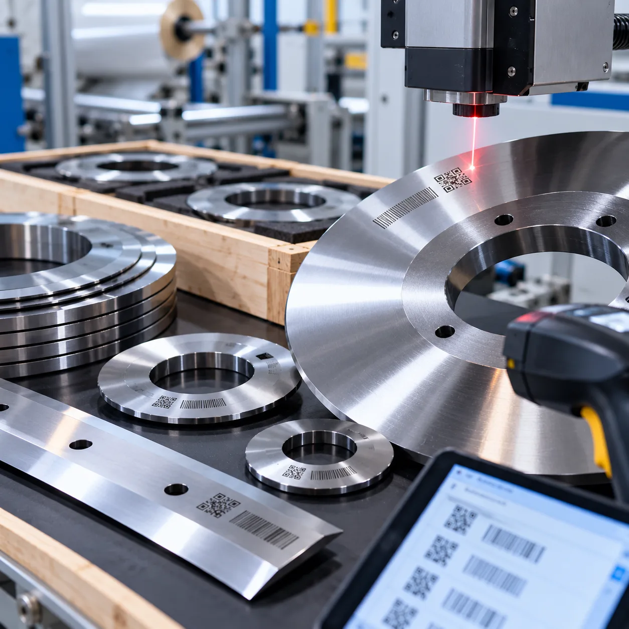
- Store in dedicated, padded racks: Never stack bare knives face-to-face. Store circular blades horizontally on wooden or polyurethane-sleeved shelving with protective dividers to eliminate accidental edge impact.
Frequently Asked Questions About Rotary Knife Slitting
What is the difference between rotary slitting and roll shearing?
Both methods use circular tooling, but their primary purpose and machine configurations differ:
| Feature | Rotary Knife Slitting | Roll / Rotary Shearing |
|---|---|---|
| Primary Function | Dividing wide master coils into multiple narrow mults simultaneously | Edge trimming, sizing, or single-line cutting |
| Arbor Setup | Multiple tool steel circular blades separated by precision tooling spacers | Usually a single pair of opposed cutting heads |
| Tooling Engagement | Continuous synchronized shearing across multiple passes | Single continuous cut along strip edges or cross-cut sections |
Understanding how rotary knife cutters work for metal slitting comes down to the synchronized, multi-cut shearing action across parallel arbors, whereas roll shearing focuses on localized edge sizing.
How often should industrial rotary slitter knives be reground?
We recommend scheduling knife regrinds based on processed tonnage and edge inspection rather than waiting for visible edge failure.
- Preventive schedule: Regrind after a set volume (e.g., every 500–1,000 tons of carbon steel, or 200–400 tons of abrasive stainless).
- Visual inspection: Pull tooling for service as soon as the cutting edge develops a radius of 0.03 mm to 0.05 mm.
- Cost benefit: Removing 0.05 mm during routine regrinding extends total knife life far longer than grinding off 0.50 mm after severe micro-chipping occurs.
Can the same rotary knife geometry cut aluminum and high-tensile steel?
No. While you can use high-performance shear slitting knives across different materials, you cannot use identical clearance settings and bevel profiles.
- Soft Aluminum: Requires tighter horizontal knife clearance (roughly 5% to 8% of metal thickness) and sharp knife profiles to prevent deep rollover and heavy burrs.
- High-Tensile Steel: Requires wider clearance (10% to 15%+ of thickness) and impact-resistant tool steel to absorb high shearing forces without chipping the blade edges.
Why do stripper ring hardness and diameter affect edge quality?
Stripper rings do more than eject the slit mults; they control how the metal strip enters and exits the shearing zone.
- Ring Diameter: Must match the vertical knife overlap. If the outer diameter is too small, the metal strip lifts before full separation, causing ragged fractures. If it is too large, the strip distorts under heavy downward pressure.
- Durometer (Hardness): Soft rings (60–70 Shore A) work best on light-gauge or surface-sensitive metals to stop scuffing. Harder rings (80–90 Shore A) provide the rigid hold-down force needed on heavy-gauge materials to stop edge camber and strip twist.
Related Sources
- https://www.metalformingmagazine.com/article/?/coilsheet-handling/slitting/proper-slitter-tooling-maintenance-and-setup
- https://www.thefabricator.com/thefabricator/article/coilsheettooling/troubleshooting-slitting-operations
- https://www.redbudindustries.com/slitting-lines/
- https://www.braner.com/equipment/slitting-lines/
- https://www.asko.com/rotary-slitter-knives-technical-support/