
Struggling with edge burrs, material dust, or frequent blade wear on your production line?
The truth is, achieving clean, high-speed cuts comes down to one critical factor: a precise slitter knife setup.
In this guide, you'll learn the exact best practices to master your slitter knife setup for flawless, high-precision slitting on every run.
Let's dive right in.
The Core Geometric Parameters of Slitter Knife Setup
Mastering rotary shear slitting requires absolute control over three fundamental geometric variables: horizontal clearance, vertical overlap, and cant angle. In our experience on the production floor, more than 85% of edge defects—such as burrs, excessive dust, and premature blade dulling—trace directly back to improper alignment across these three axes.
Male Blade
↓
Cant Angle (Toe-In): Angular inclination of the male blade
Horizontal Clearance (Side Gap): Lateral gap between the male and female blades
Overlap Depth (Penetration): Vertical penetration of the male blade past the female blade
Female Anvil: Lower supporting / cutting blade
1. Horizontal Clearance (Side Gap) Calculation and Tolerances
Horizontal clearance is the physical lateral gap between the cutting edges of the upper male slitter blade and the lower female anvil knife. Setting this gap correctly balances shearing force and tensile break-away:
- Too Tight (Zero or Negative Gap): Causes heavy metal-to-metal friction, edge micro-chipping, accelerated tooling wear, and localized thermal expansion.
- Too Loose (Excessive Gap): Forces the substrate to bend rather than shear, resulting in edge burrs, tensile tearing, and excessive slitting dust.
- Standard Calculation: Set the horizontal clearance as a percentage of substrate thickness (T):
- Thin Gauge Films (BOPP, PET, PE): 3% to 6% of material thickness.
- Paper & Multi-Wall Board: 6% to 10% of material thickness.
- Non-Ferrous Foils & Light Metals: 8% to 12% of material thickness.
2. Vertical Overlap (Penetration Depth) Settings
Vertical overlap defines how far the male knife enters below the outside diameter (OD) rim of the female knife. Excessive penetration increases the contact chord length, inducing unnecessary side-load strain and blade deflection.
- Thin Packaging Films (< 50 µm): 0.010" – 0.020" (0.25 mm – 0.50 mm). Minimal penetration prevents web stretching and edge pinch.
- Paper & Board Stock: 0.025" – 0.040" (0.65 mm – 1.00 mm). Ensures complete structural shear through fibrous matrix layers.
- Rigid Foils & Heavy Laminates: 0.015" – 0.030" (0.40 mm – 0.75 mm). Provides clean fracture control without edge rolling.
3. Cant Angle and Toe-In Calibration
The cant angle (or toe-in angle) ensures the male blade contacts the female knife at only a single, precise shear point at the cutting point.
- The Mechanism: Tilting the male knife slightly into the shear point creates the correct lead-in cutting geometry while pulling the trailing edge away from the female blade.
- Eliminating Heel Drag: Without adequate toe-in, the trailing edge (heel) of the male knife rubs against the female hub. This heel drag generates extreme heat, edge galling, and slitter dust.
- Target Calibration: Maintain a cant angle between 0.25° and 0.50° (15 to 30 arc-minutes). Angles above 0.75° concentrate excessive side pressure on the knife tip, leading to carbide or tool steel edge fractures.
Slitter Geometry Quick Reference Table
| Substrate Type | Thickness Range | Horizontal Clearance (% of Thickness) | Vertical Overlap Depth | Target Cant Angle |
|---|---|---|---|---|
| BOPP / PET / LLDPE | 12 – 100 µm | 4% – 6% | 0.010" – 0.015" (0.25 – 0.38 mm) | 0.25° (15') |
| Coated & Kraft Paper | 40 – 300 gsm | 7% – 10% | 0.025" – 0.035" (0.65 – 0.90 mm) | 0.35° (20') |
| Aluminum / Copper Foil | 20 – 150 µm | 8% – 12% | 0.015" – 0.025" (0.38 – 0.65 mm) | 0.30° (18') |
| Heavy Board / Laminates | > 300 gsm | 8% – 12% | 0.030" – 0.045" (0.75 – 1.15 mm) | 0.50° (30') |
Pre-Setup Inspection: Eliminating Mechanical Runout

A precise slitter knife setup starts before a single blade touches the arbor. If mechanical runout is present on your shafts, no amount of lateral blade adjustment will stop edge burrs or slitting dust. We treat pre-setup inspection as mandatory shop-floor protocol to guarantee cutting consistency across the entire web.
Measuring Arbor and Shaft Total Indicated Runout (TIR)
Radial and axial runout compound across the shaft length. Any variance over tolerance creates blade wobble, leading to intermittent side-load pressure and premature edge failure.
- Target Radial Runout: Keep radial TIR under 0.0002" (0.005 mm) along the bearing journals and tooling barrel.
- Target Axial (End-Play) Runout: Maintain axial float below 0.0001" (0.0025 mm) against the locking shoulder.
- Measurement Method: Mount a calibrated dial test indicator with a magnetic base to the machine frame. Sweep the full operational length of both top and bottom arbors while rotating the shafts slowly by hand.
Arbor Cleaning, Deburring, and Fretting Inspection
Contaminants as thin as a single micron alter blade perpendicularity.
- Solvent Wipe: Clean the bare shafts using an industrial degreaser to remove built-up oil, resin, and adhesive residue.
- Fretting and Galling Checks: Run an Arkansas stone lightly over the arbor surface. Any raised burr, score mark, or fretting corrosion must be stoned flush immediately.
- Keyway Inspection: Inspect the drive keys and keyways for taper or deformation that could cock the tooling off 90 degrees.
| Inspection Point | Tooling Used | Max Tolerance | Action on Failure |
|---|---|---|---|
| Arbor Radial TIR | Dial Indicator | 0.0002" (0.005 mm) | Polish journal / replace bearings |
| Shoulder Squareness | Dial Indicator | 0.0001" (0.0025 mm) | Re-grind shoulder true |
| Blade Parallelism | Micrometer | 0.00008" (0.002 mm) | Surface regrind / discard tooling |
| Spacer Thickness | Drop Gauge | ±0.0001" (0.0025 mm) | Segregate and replace spacer set |
Checking Male and Female Slitter Knives
We never mount dull, chipped, or contaminated knives onto an arbor.
- Cutting Edge Integrity: Inspect cutting edges under 10x optical magnification. Micro-chipping along the primary bevel or female anvil corner will quickly tear sensitive webs.
- Flank Wear: Check the vertical reference face of the knives for rub marks, scoring, or material pickup. Choosing the correct slitter blade material prevents rapid flank gauling and micro-cracking under heavy side loads.
- Bore Fit: Ensure the knife inside diameter (ID) matches the arbor outside diameter (OD) within standard sliding clearance (typically +0.0005" to +0.0010"). A loose bore forces the knife eccentric under cut.
Precision Spacer and Shim Parallel Thickness Verification
Spacers dictate your slit width accuracy and parallel knife engagement. Defective spacers tilt the blades and ruin lateral clearance.
- Parallelism Verification: Measure each spacer at four quadrants using a calibrated outside micrometer. Thickness variation across opposite points must not exceed 0.0001" (0.0025 mm).
- Face Flatness: Check spacer contact faces for dirt, nicks, or concave dishing caused by over-torquing.
- Clean Stacking: Wipe down both faces of every spacer with lint-free wipes before sliding them onto the arbor. One trapped speck of dust can cock your entire tooling train out of square.
Step-by-Step Rotary Shear Slitter Setup Protocol (SOP)
Executing a precise slitter knife setup requires a disciplined sequence. Skipping steps or eyeballing tolerances leads directly to bad edges, scrap, and damaged tooling. When mounting precision sheet metal slitter knives or standard converting blades, we follow this shop-floor standard operating procedure to guarantee clean cuts on every run.
Shear Slitter Setup SOP
1. Lower Knives
↓
2. Upper Zeroing
↓
3. Horizontal Gap
↓
4. Overlap Depth
↓
5. Side Load
↓
6. Creep Test
Step 1: Locking Down Lower (Female) Knives & Spacers
We always build the bottom arbor first because the lower knives establish the fixed cutting line.
- Slide tooling onto the cleaned bottom arbor in the exact pattern specified by the setup sheet, alternating female anvil knives and precision ground spacers.
- Wipe every mating face with a lint-free cloth during assembly to prevent dirt-induced runout.
- Lock the arbor clamp nut to the specified torque rating using a calibrated torque wrench. Uneven axial compression bows the shaft and ruins blade squareness.
Step 2: Calibrating Upper (Male) Blade Positioning & Zero-Referencing
Once the bottom shaft is locked, align the upper knife holders to match the lower cutting edges.
- Position the upper knife holders on the top shaft or crossbeam, aligning each male blade roughly with its corresponding female anvil.
- Establish the zero reference: Bring the upper blade down gently until it aligns flush against the female knife's face with zero side gap and zero overlap, without letting the sharp cutting edges collide.
- Lock the axial positioner on the top holder to set this baseline reference point.
Step 3: Setting Horizontal Side Clearance with Precision Gauges
Setting the correct slitter blade clearance prevents burrs on heavy materials and tear-outs on thin gauges.
- Insert a non-marring brass or plastic feeler gauge (or standard feeler stock for heavy tooling) between the vertical faces of the top and bottom knives.
- Adjust the holder's micro-adjust screw until the gap matches the material spec (typically 5% to 10% of material thickness).
- Tighten the cross-locking clamp and re-verify the gap across the blade circumference.
| Substrate Type | Target Horizontal Side Gap |
|---|---|
| Thin Film / Foil | 0.0000" – 0.0002" (Zero to light kiss) |
| Paper & Board | 0.0005" – 0.0015" (Material dependent) |
| Metal Strip / Coil | 6% – 10% of gauge thickness |
Step 4: Setting Vertical Overlap Depth using Micrometer Stops
Excessive vertical overlap causes heel drag, slitting dust, and premature blade dulling.
- Use the vertical micrometer stop on each knife holder to lower the male blade into the female anvil.
- Set the penetration depth according to the material chart—never exceed what is required to cleanly part the web.
- Lock the vertical stop collars securely to prevent blade drift under high web tension.
Step 5: Adjusting Side-Load Contact Pressure
For spring-loaded or pneumatic knife holders, correct side-load pressure maintains knife contact without friction burning.
- Set the pneumatic side-load regulator to the lowest pressure that maintains continuous contact during web deflection (typically 15–30 psi depending on holder design).
- For spring-loaded tooling, dial the spring compression to provide just enough force to prevent the blades from separating under shear stress.
- Ensure cant angles are locked between 0.25° and 0.5° to maintain single-point cutting contact at the nip.
Step 6: Static Rotation and Dynamic Creep-Speed Web Testing
Never ramp directly to full line speed without validation.
- Static Hand Turn: Disengage the drives and rotate the shafts by hand for one full 360° turn. Listen for binding, metal-on-metal scraping, or uneven friction spots.
- Creep Speed Feed: Thread the lead material through the slitting section and run the slitter at creep speed (5–10 m/min).
- Edge Inspection: Stop the web immediately and inspect the slit edge using a 10x optical loupe to verify a clean fracture line, zero burrs, and no polymer dust or metal slivers before ramping up to standard production speed.
Tailoring Slitter Knife Setup to Different Slitting Methods
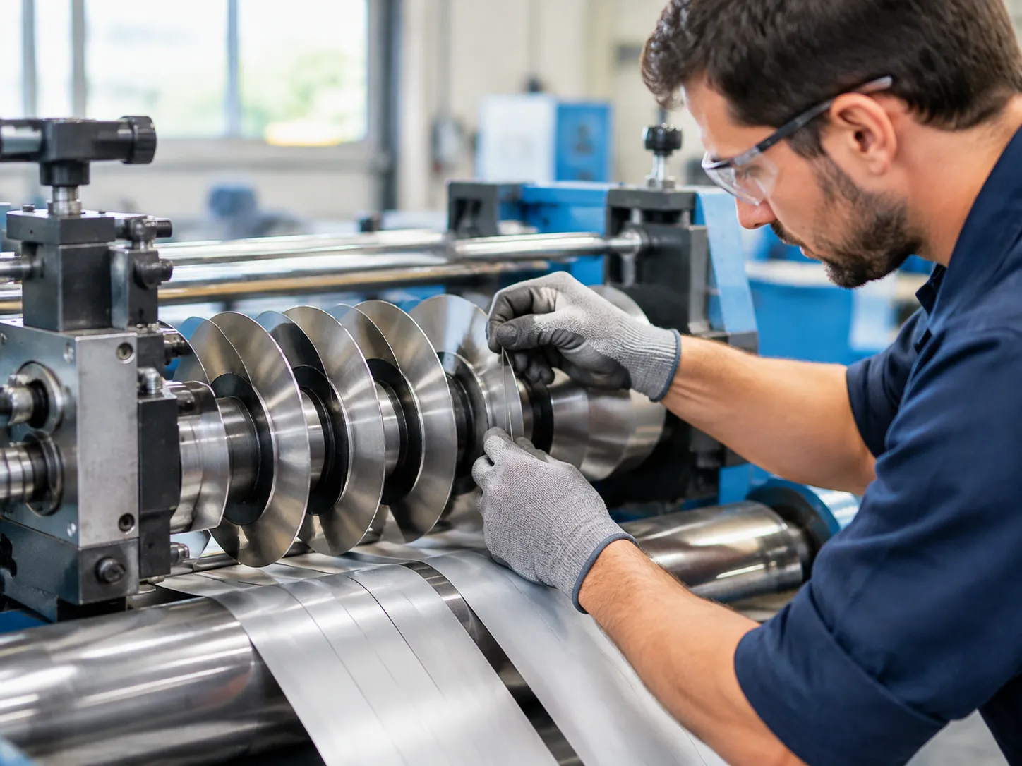
Every converting line handles web tension, blade engagement, and friction differently. We dial in the slitter knife setup based on the three primary converting methods to stop edge defects before they start.
| Slitting Method | Tooling Engagement | Key Setup Control | Best Substrates |
|---|---|---|---|
| Rotary Shear | Male and female blade overlap | Cant angle, horizontal clearance, side-load | Paper, board, metal foil, multi-layer laminates |
| Razor Slitting | Slotted blade in-air or supported in-groove | Penetration depth, blade angle, oscillation | Thin gauge films (BOPP, PET), lightweight foils |
| Crush / Score Cut | Radius-edge blade loaded against anvil roll | Pneumatic vertical load, anvil hardness match | Non-wovens, textiles, pressure-sensitive tapes |
Rotary Shear Slitting: Wrap vs. Tangential Alignment
When mounting industrial shear slitting knives, web path geometry dictates stability at the cut point:
- Wrap Slitting: The web physically wraps over the lower female knife before the cut point. We use this setup for heavy paperboards and stretchy films. It stabilizes the material against the anvil face, preventing web flutter and uneven slitting width.
- Tangential (Kiss) Slitting: The web merely skims the tangent point between male and female knives. We utilize tangential setups for rapid job changeovers and materials prone to scratch marks. Because the web lacks mechanical support, we maintain strict side-load tolerances and minimum overlap to prevent the blade from pushing the web sideways.
Razor Slitting: In-Air vs. In-Groove Positioning
Razor setups deliver razor-sharp edges on thin films, but blade deflection destroys slit quality instantly:
- Razor-in-Air: Used for thin, non-abrasive films. We mount the blade at a 45° to 60° angle to reduce drag. Without back support, incoming web tension must remain exceptionally uniform to avoid nicked edges.
- Razor-in-Groove: The razor blade penetrates into a grooved roller or grooved spacer rings. This supports the substrate on both sides of the slit. We set penetration just deep enough to clear the web layer—typically 0.5 mm to 1.0 mm into the groove—avoiding blade flex.
- Blade Oscillation: We program continuous transverse oscillation where possible. Shifting the blade side-to-side across the web path distributes wear, preventing localized heat buildup and premature dulling.
Score / Crush Cut Slitting: Vertical Load and Anvil Hardness
Crush cutting splits the substrate by pinching it against a hardened steel sleeve under pneumatic pressure. Our setup focuses on preventing anvil grooving while ensuring clean edge separation:
- Anvil Hardness Matching: We pair crush cut blades (typically 60–62 HRC) with anvil sleeves hardened to 64–66 HRC. The anvil must always be harder than the blade to prevent score lines from imprinting onto the roll surface.
- Pneumatic Load Calibration: We run the lowest air pressure required to yield a clean cut. Excessive downforce crushes the web fibers, creates heavy edge burrs, and flattens the blade tip within hours. Always calibrate knife holders with precision air regulators down to 0.1 bar increments.
Substrate-Specific Slitter Knife Setup Guidelines
Flexible Packaging Films (BOPP, PET, PE, Laminates)
Thin polymer films require high sharpness, minimal horizontal clearance, and shallow penetration to prevent web stretching, tearing, or scalloped edges:
Clearance and Overlap: Set horizontal clearance to near-zero (light kissing contact) and vertical overlap shallow between 0.010" and 0.025" (0.25 mm – 0.65 mm).
Cant Angle: Keep the cant angle narrow between 0.25° and 0.50° to minimize side friction while ensuring positive point contact.
Tooling Tip: High-speed web applications perform best with precision-ground packaging machine knives with mirror-polished bevels to prevent film drag and polymer adhesive buildup.
Paper and High-Basis Board Stock
Fibrous substrates generate high abrasive wear and loose fiber debris if penetration depth or side gap is misaligned:
Clearance and Overlap: Set vertical overlap deeper, around 0.030" to 0.060" (0.75 mm – 1.50 mm), to achieve clean, complete fiber separation without crushing.
Horizontal Clearance: Maintain a gap of 5% to 8% of the material thickness. Setting the gap too wide pulls loose fibers instead of shearing them.
Side-Load Pressure: Apply firm side-load pressure to prevent the male blade from deflecting away from the anvil knife under heavy board resistance.
Metal Coil and Heavy Foils
Slitting metal strip and heavy foils relies on controlled fracturing rather than continuous pure shearing:
The 1/3 Shear, 2/3 Break-Away Ratio: Calibrate the tooling to produce approximately 1/3 cut depth (penetration) followed by a clean 2/3 natural tensile fracture.
Horizontal Gap: Calibrate the horizontal clearance between 7% and 12% of the metal gauge. Setting clearance too tight causes secondary shearing and rapid knife wear; setting it too loose generates severe edge rollover and excessive burrs.
Tooling Selection: We recommend hardened tool steel or carbide-tipped shear blades capable of absorbing high shock loads without micro-chipping along the cutting edge.
Substrate Setup Matrix
| Substrate Type | Vertical Overlap | Horizontal Clearance | Cant Angle | Failure Risk if Setup Is Incorrect |
|---|---|---|---|---|
| Thin Films (BOPP, PET, PE) | 0.010" – 0.025" | Near 0 (0.0002" – 0.0005") | 0.25° – 0.50° | Edge stretching, tears, scalloping |
| Paper & Kraft Board | 0.030" – 0.060" | 5% – 8% of thickness | 0.50° – 0.75° | Dust generation, fiber pullout, rough edges |
| Metal Foil & Light Coil | 1/3 of thickness | 7% – 12% of thickness | 0.00° – 0.25° | Heavy burrs, double shear, edge roll |
Troubleshooting Common Edge Defects via Slitter Knife Setup Adjustments
When slit edge quality drops, the root cause almost always traces back to improper geometry, worn tooling, or excessive side-load pressure. We troubleshoot and correct the most frequent converting defects by adjusting the slitter knife setup parameters directly on the arbor.
Fixing Slitter Dust and Debris Generation
Excessive slitting dust indicates tearing or crushing rather than clean shearing. We systematically isolate the cause using these setup adjustments:
- Reduce excessive vertical overlap: When male blades penetrate too deep into the female anvil knife, web deflection creates friction and tears fibers or polymers. Back off overlap to standard material specifications.
- Tighten horizontal clearance: A gap that is too wide forces the web to bend before breaking, producing fine particle debris. Reset the side clearance to proper material-thickness ratios.
- Eliminate heel drag: Confirm that the cant angle is aligned correctly so the back of the upper blade does not scrub against the cut edge of the web.
Eliminating Burrs on Slit Edges
A visible or tactile slit edge burr signals improper shear line mechanics or dull cutting edges:
- Adjust side-load contact pressure: Insufficient side-load pressure allows the upper blade to push away from the lower knife under load, creating rollover burrs. Increase spring or pneumatic side load to maintain consistent point-of-cut contact.
- Check for blade dulling: Inspect edges under magnification. Running dull tooling past its regrind threshold creates immediate rollover burrs. Upgrading to a hardened 150mm slitter blade precision cutting tool ensures clean edge separation across long production runs.
- Verify arbor runout: Ensure total indicated runout (TIR) on both shafts remains within strict operating limits (under 0.005 mm / 0.0002"). Runout causes intermittent gap variation that generates alternating burrs.
| Defect Observed | Primary Root Cause | Immediate Setup Correction |
|---|---|---|
| Heavy Edge Burr | Excessive horizontal gap or dull edge | Reduce side clearance; replace or regrind blades |
| Slitting Dust / Flakes | Over-penetration or heel interference | Reduce vertical overlap; realign cant angle |
| Edge Roll / Curled Slit | Over-engagement or high side pressure | Decrease penetration depth; lower contact load |
| Chipped Blade Edges | Excessive side loading or arbor runout | Reduce lateral force; calibrate shaft TIR |
Correcting Edge Roll and Serpentine Cuts
Edge roll and wandering slit lines disrupt downstream winding and converting operations:
- Correcting edge roll: Edge roll occurs when excessive vertical overlap forces the slit strip into the female knife pocket. Raise the top arbor to minimize penetration depth while maintaining a stable shear point.
- Correcting serpentine cuts: Weaving cut lines typically stem from loose arbor locking collars, worn spacers, or dynamic shaft deflection. Re-torque locking nuts to manufacturer specifications and verify that spacers sit perfectly parallel without dirt or debris on their mating faces.
- Addressing feed interruptions: If edge roll leads to web jamming around the cutter head, check our slitter blade jam troubleshooting methods to clear the path safely and reset knife alignment.
Preventing Chipped Blade Edges and Tooling Failure
Micro-chipping and premature blade edge failure escalate tooling replacement costs and cause sudden line shutdowns:
- Lower excessive side-load force: Forcing male and female knives together with excessive lateral force generates extreme friction and thermal stress, leading to brittle edge fractures. Set side pressure to the bare minimum needed for a clean cut.
- Eliminate blade clash during engagement: Ensure upper and lower knives never contact face-to-face during machine positioning or indexing. Always verify horizontal side clearance before setting vertical overlap.
- Dampen machine vibration: Check bearings and drive couplings for backlash or wear that transfers impact shock loads directly to the cutting edges.
Standardization and Setup Quality Control
Repeatable cut quality across shifts requires removing guesswork from your slitter knife setup. We treat knife setup not as an art left to individual operator preference, but as a standardized, documented manufacturing process backed by strict quality verification.
Developing Standardized Machine Setup Run Cards
We implement recipe-based run cards for every substrate grade and caliper running through the slitting line. These cards lock in exact mechanical settings so any operator can reproduce clean, burr-free edges on the first pass.
| Parameter on Run Card | Target Value Record | Why It Matters |
|---|---|---|
| Material & Gauge | Substrate type, film thickness, or metal gauge | Dictates penetration depth and side gap |
| Blade Part Numbers | Upper male and lower female tooling IDs | Ensures correct metallurgy and bevel profile |
| Horizontal Clearance | Measured gap in inches or millimeters | Prevents slitting dust, burrs, and premature blade wear |
| Vertical Overlap | Depth of penetration setting | Maintains proper shear point without web pinching |
| Side-Load Pressure | Calibrated spring or pneumatic load (psi/bar) | Eliminates knife deflection under web tension |
| Spacer Sequence | Exact stack-up layout from arbor shoulder | Guarantees precise slit widths and zero cumulative runout |
Tooling Lifespan Tracking and Regrinding Thresholds
Running dull or chipped blades to failure ruins web quality, generates excessive debris, and damages downstream tooling. We track total linear footage and running hours per blade set, pulling knives based on measurable wear criteria rather than subjective visual checks:
- Edge Wear Land: Pull blades when cutting-edge flank wear exceeds 0.002 in (0.05 mm).
- Slit Quality Degradation: Immediate blade replacement if edge burr height exceeds substrate specifications or visible edge fraying appears.
- Micro-Chipping: Any nick or chip visible under a 10x shop loupe warrants an immediate tool swap.
- Regrinding Limits: Follow our documented knife maintenance best practices to ensure reground blades maintain original hardness and bevel angles without thermal micro-cracking.
- Inspection Checks: Verify all sharpened and new tooling against incoming quality control protocols for outer diameter runout, thickness parallelism, and surface finish.
Safe Knife Handling and Changeover Procedures
Precision blades are fragile and dangerous if mishandled. A single dropped tool or accidental arbor collision chips carbide and tool steel edges instantly, ruining your setup before the line even starts.
- Use Protective Sleeves & Caddies: Keep edge guards on all male blades and female rings until the final clearance adjustment stage. Never stack bare knives directly on top of each other.
- Arbor Installation Protection: Use brass or composite guide sleeves over threaded arbor ends during loading to prevent nicking the knife bore or scratching the precision shaft surface.
- Torque Sequence Discipline: Tighten locking nuts and collar rings using a calibrated torque wrench in a staged, uniform sequence to prevent uneven axial clamping pressure and induced blade wobble.
- Zero-Contact Gap Checks: Never use metal tools or feeler gauges directly on sharpened cutting apexes without proper gauge-handling technique to avoid edge rolling.
Frequently Asked Questions (FAQs) About Slitter Knife Setup
How do I know if my slitter blade overlap is set too deep?
You can identify excessive vertical overlap by looking for specific operational warning signs:
Accelerated edge wear and heat: Friction increases dramatically across the contact arc, leading to localized heat buildup and rapid dulling of both the male slitter blade and female anvil knife.
Edge deformation: Overly deep penetration causes stretching, scalloped edges, or pinched slit profiles instead of a clean, square cut.
Increased drive load: Machine motors draw higher amperage due to continuous mechanical drag.
In rotary shear setups, we recommend keeping vertical penetration minimal—typically between 0.015" and 0.035" (0.38 mm to 0.9 mm) depending on web caliper—just enough to cleanly sever the substrate without creating unnecessary blade interference.
What is the ideal cant angle for rotary shear slitting?
For most industrial converting applications, the ideal cant angle (toe-in) ranges between 0.25° and 0.5° (15 to 30 arcminutes).
Maintaining this precise angle ensures single-point shear contact at the cutting zone. If the cant angle is set too wide (over 1°), the rear edge of the blade creates heel drag against the female ring, causing micro-chipping and rough slit edges. If set completely parallel (0°), the blades are prone to chatter and erratic side-to-side deflection under web tension.
Why does improper knife clearance cause excessive slitting dust?
Slitting dust is almost always generated when material is crushed or torn rather than sheared:
Clearance set too wide: The web slips into the horizontal gap between the upper and lower knives, stretching fibers or polymer chains until they fracture irregularly, creating airborne debris and ragged slit edges.
Clearance set too tight: Excessive side-load contact pressure leads to blade scuffing and micro-flaking of the cutting edge, introducing metallic particles directly into the web path.
Using premium circular slitter knives with precision-ground tolerances and setting horizontal clearance to 5%–10% of material thickness eliminates dust generation at the source.
What is the maximum allowable arbor runout for precision slitting?
For high-speed, tight-tolerance slitting, the maximum allowable Total Indicated Runout (TIR) on both the arbor shaft and mounted tooling is 0.0002" to 0.0005" (5 to 12 microns).
Radial or axial runout exceeding this threshold causes the horizontal side gap to fluctuate dynamically with every revolution. This cyclical variation produces repeating slit edge burrs, premature blade chipping, and poor roll structure. For demanding foil and film applications, investing in precision-balanced slitting knives and calibrated spacers keeps your entire arbor assembly running true within sub-micron tolerances.